On this page
In brief: The right end effector is chosen by contact geometry, surface condition, process forces and the signals that confirm the grip, not by payload alone.
The gripper is the only part of the robot that touches the product, and it is often specified last. It has to be engineered for one part, one surface and one cycle, including the moments when a pick goes wrong. This guide explains what holding force has to cover, where each gripping principle fits, and what to test before the design is frozen.
Separate holding force from payload
Payload says what the wrist can carry. Holding force says whether the part stays where it was gripped. The grip has to resist gravity, the robot’s acceleration and braking, an emergency stop and any process force, with a calculated margin. When jaws clamp a part from the sides, or suction cups carry it on a vertical face, friction holds the load, and friction changes with oil, moisture and surface finish. Schmalz’s published design notes for suction cups state that no generally valid friction coefficient can be given and that it has to be determined by tests, base the calculation on the worst load case, and require a higher safety factor for porous, rough or oiled workpieces than for smooth, dense ones.
Compare the four approaches on their merits
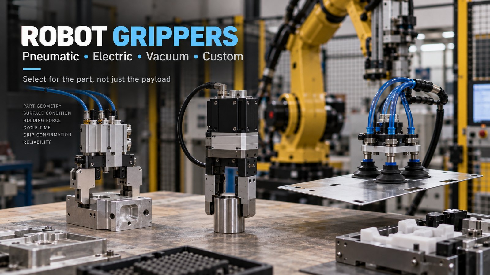
Pneumatic grippers are mechanically simple and fast, and they suit plants where compressed air is already available; grip force follows the supply pressure, and the jaws typically move between two end positions. Electric grippers usually let the program set force, position and speed and can report where the jaws are. Vacuum suits parts with a broad surface that can be sealed and is harder to apply to porous, oily or strongly curved surfaces. A custom tool is sometimes the only answer for hot, fragile or highly variable parts. Each choice brings its own upkeep: air preparation and leaks, worn jaws and cups, and cables and hoses that flex on every cycle.
Design for the missed pick
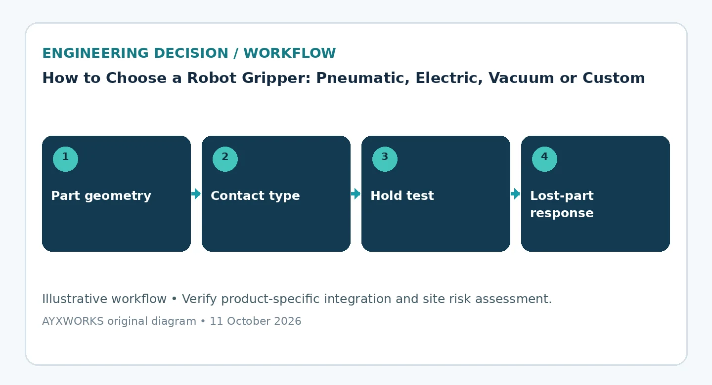
The cell has to know whether the jaws closed on air, whether the part is skewed and whether it stayed attached during travel. That takes sensing, such as jaw position, a vacuum switch or a part-present sensor, and a defined rule for what happens next: a blind second attempt can turn a missed pick into a damaged part or a collision. Decide also what the gripper does when air or power is lost. A part released at the wrong moment is a hazard, so that behaviour belongs in the risk assessment of the cell. Clearing a dropped or jammed part usually means someone entering the cell, and OSHA notes that studies indicate many robot accidents occur during non-routine operating conditions such as programming, maintenance, testing, setup or adjustment.
Prototype the worst cases, not only the nominal part
Test the extremes of the part tolerance, worn and contaminated surfaces, unexpected orientations, the temperature the gripper reaches at production rate, and the release into the destination fixture. Write down what is acceptable for slip, marking, repeatability and wear before the trial, so that the result is a pass or a fail, not an impression. Gripper selection is a small mechanical design project, not a catalogue shortcut.
Checklist before committing budget or scope
- Part geometry, mass, surface finish and contamination in the worst condition, for every variant.
- Holding-force calculation covering acceleration, emergency stop and process forces.
- Gripping principle, its air or electrical supply and its controller interface.
- Sensing for part present, part lost and part skewed, with a defined retry and fault response.
- Behaviour on loss of air or power considered in the risk assessment.
- Dress pack routing, changeover, spare parts and cleaning plan.
What this guide does not establish
This guide is a planning aid. It is not a test report, a product certification or a guarantee of performance. The manufacturer page cited below is an example of how one supplier publishes its design rules; factors and limits for any other product must come from that product’s own documentation. The gripper is part of the robot application, so its hazards have to be covered by the risk assessment of the complete cell and verified on the real system by suitably qualified people. ISO 10218-2 is paywalled and is not summarised clause by clause.
Sources and further verification
- Schmalz — Theoretical Holding Force of a Suction Cup, Vacuum Knowledge (undated; accessed 2026-10-12).
- OSHA — Robotics: Overview, Safety and Health Topics (undated; accessed 2026-10-12).
- ISO — ISO 10218-2:2025, Robotics — Safety requirements — Part 2: Industrial robot applications and robot cells (2025-02; accessed 2026-10-11).
Next useful step
If you are choosing a gripper for a specific part, bring sample parts in their worst condition (oily, hot, at the tolerance limits), the pick and place positions, the cycle-time target and the air and electrical supply available to the Robotics & Automation page and solution finder. Projects taken on from there are scoped and delivered through Eurobots/ReBots, and they start with feasibility and responsibility boundaries, not with an assumed turnkey installation. The engineering background to these guides is in the AYXWORKS portfolio.
Image credit: ayxworks — Original / rights held.