On this page
In brief: A suitable robot can load a blank into a machine. Reliable automatic tending depends on the clamping state, door control, chips and coolant, part detection and recovery after an incomplete transfer. Check these interfaces before selecting an arm.
Why the robot is rarely the problem
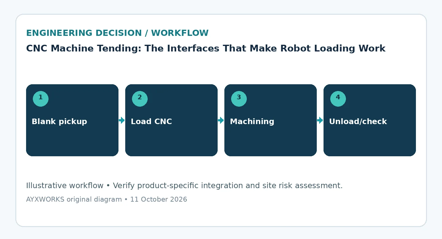
Most six-axis robots can carry a blank through a machine door. Whether the cell then runs unattended is decided by everything the robot has to agree on with other equipment. Where is the part? Has the chuck or fixture really opened or clamped? Has the machine finished its program? Each answer is a signal or a mechanical assumption with an owner: the machine builder, the workholding supplier, the integrator or the plant. Each can be wrong in a way that a demonstration with ten clean parts will not reveal.
Map one complete cycle, signal by signal
Write the cycle as a list of steps and, for each step, the confirmation that permits the next one: blank available at the pickup, part gripped, door open, workholding open, part seated, workholding clamped, robot clear of the machine, door closed, cycle start, cycle complete. For every confirmation, name its source (a sensor, a CNC output, a PLC bit) and state what the cell does if it never arrives.
Take signal names and wiring from the machine builder’s interface documentation for that exact machine and control option. Robot interfaces differ between builders and between models, so do not assume that an M-code, an automatic door or a clamp confirmation exists because another machine had one. If a function is missing, that is a scope item with a cost, not a detail to settle during commissioning.
Design gripper and workholding for the bad part
A machined part leaves the spindle wet with coolant, carrying chips, sometimes warm and often with burrs, while the blank has a wider dimensional spread than the finished part. The gripper must hold both, so check gripping faces and gripping force against the worst case rather than the nominal drawing. Decide how the cell detects a dropped part, a part loaded the wrong way round, a chip under the locating face and a part still in the chuck when the next one arrives.
Treat recovery as a designed sequence
A cell stopped halfway through loading cannot simply restart at the first step, because the part may be in the gripper, in the chuck or on the floor. For each step, define what state the robot and the machine record, how an operator establishes where the part actually is, and what must be reset before automatic running resumes. OSHA’s robotics overview notes that many robot accidents occur during non-routine operating conditions such as programming, maintenance, testing, setup or adjustment, and recovery work fits that description. Safeguarding and safety functions are a separate, validated design that follows from the risk assessment of the complete robot application, the subject of ISO 10218-2:2025.
Checklist before committing budget or scope
- Part family, blank tolerance and presentation method are defined, including how blanks are replenished.
- Machine interface, door and workholding functions are confirmed in the builder’s documentation for the exact machine and control.
- The gripper has been checked on wet, chip-covered and out-of-tolerance parts, and lost-part and misload detection is defined.
- A responsibility matrix covers robot, gripper, PLC, CNC interface, door, safety, fixtures and FAT/SAT.
- Witnessed tests are agreed for misload, reset, changeover and recovery with a part left in the chuck, not only for the normal cycle.
What this guide does not establish
This is a planning aid. It reports no tests, describes no specific installation and makes no performance claim for any robot, machine tool or gripper. It does not replace the risk assessment, the safety validation or the conformity work for your cell, which must be carried out on the real system by suitably qualified people.
Sources and further verification
- OSHA — Robotics: overview page stating that many robot accidents occur during non-routine operating conditions (undated; accessed 2026-10-12).
- ISO — ISO 10218-2:2025, Robotics — Safety requirements — Part 2: Industrial robot applications and robot cells (catalogue page; 2025-02; accessed 2026-10-11).
Next useful step
If you are scoping a tending cell, write down the part family, the machine and control model, the target cycle time and the interface list above, then see the Robotics & Automation page. Projects that start there are scoped and delivered through Eurobots/ReBots, and an evaluation begins with feasibility and responsibility boundaries rather than an assumed turnkey installation. The engineering background behind these guides is in the AYXWORKS portfolio.
Image credit: ayxworks — Original / rights held.