On this page
In brief: A robot’s rated payload and reach are screening figures. Sizing a real application also depends on tool geometry, centre of gravity, inertia, the motion itself and whether collision-free poses exist.
A datasheet answers one question well: which robots are clearly too small. It does not say whether a given robot will run your part, with your gripper, in your cell, at your rate. Payload, reach and speed are each stated under conditions that an application seldom reproduces. This guide explains what each figure leaves out and what evidence to ask for before ordering.
Payload is not just the workpiece
The wrist carries everything bolted to the flange: gripper, adapter plates, sensors, valves, the dress pack and then the part. Yaskawa accordingly defines payload as the weight the robot can handle on the wrist axis including the tool, and adds that moment and inertia requirements must be met as well as mass. Doosan’s manual states that the maximum payload changes according to the distance of the centre of gravity. A long gripper holding a light part off-centre can therefore reach the moment or inertia limit of the wrist well below the rated kilograms. The centre of gravity also moves when the tool opens, closes or picks a different part, so check every state against the manufacturer’s load diagram for the exact model.
Reach is a three-dimensional problem
The catalogue reach is a geometric extreme. Check which point the manufacturer measures it to; it is commonly the wrist centre, not the tip of your tool. The figure also says nothing about whether the tool can arrive in the orientation the process needs. Near the edge of the working envelope and near singularities the wrist has little freedom left, so a point that is within reach can still be unusable when the process dictates the approach direction. Check wrist orientation, overhead obstructions, fixture access and the dress pack for all part variants, and leave maintenance clearance and safe access for people.
Cycle time belongs to the whole cell
Break the cycle into travel, grip, settle, machine wait, inspection and signal handshake. Short moves do not reach the catalogue top speed, because the robot spends them accelerating and decelerating, and a heavy or offset load can lengthen them further. Where stages overlap, the cycle is governed by sequence dependencies, such as the robot waiting for a machine door or for a PLC acknowledgement, and not by the sum of the robot’s move times. Validate a conservative program with the real tooling and the dwell time the process requires.
Prove the sizing before ordering
Ask the supplier for a load and inertia calculation for the exact arm and controller configuration, a reachability check on representative paths, and an acceptance window for cycle time instead of a single number. A nominally larger robot is not automatically the safe choice: it needs more floor space and costs more, and it can make the cell slower if access is poor. Simulation narrows the choice. A physical trial with the real tooling confirms it.
Checklist before committing budget or scope
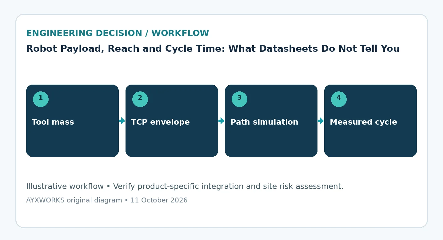
- Mass, centre of gravity and inertia for every tool and load state, checked against the manufacturer’s load diagram.
- Tool centre point (TCP) poses for every pick, process and place position, with a collision-free path between them.
- Dress pack routing and maintenance clearance around the cell.
- Cycle breakdown, including PLC and process waits.
- Controller options and mounting position confirmed in the manuals for the exact model.
- Simulation findings verified in an appropriate physical trial.
What this guide does not establish
This guide is a planning aid. It is not a test report, a product certification, a legal assessment or a guarantee of performance. The manufacturer documents cited below are examples of how load limits are published; the limits for any other model must come from that model’s own manual. Final hardware selection, functional safety, machinery compliance and commissioning have to be verified on the real system by suitably qualified people. The ISO standards are paywalled; they are listed for the safety requirements that apply to the robot and to the complete application, not summarised clause by clause.
Sources and further verification
- Yaskawa Motoman — Allowable Load and Payload, Knowledge Center article (updated 2024-02-12; accessed 2026-10-12).
- Doosan Robotics — User Manual V3.2.1, M/H Series: Max. Payload within operating space (undated; accessed 2026-10-12).
- ISO — ISO 10218-1:2025, Robotics — Safety requirements — Part 1: Industrial robots (2025-02; accessed 2026-10-11).
- ISO — ISO 10218-2:2025, Robotics — Safety requirements — Part 2: Industrial robot applications and robot cells (2025-02; accessed 2026-10-11).
Next useful step
If you are sizing a robot for a specific part, bring the part and tool masses, a sketch of the gripper, the pick and place positions, the cycle-time target and the floor constraints to the Robotics & Automation page and solution finder. Projects taken on from there are scoped and delivered through Eurobots/ReBots, and they start with feasibility and responsibility boundaries, not with an assumed turnkey installation. The engineering background to these guides is in the AYXWORKS portfolio.
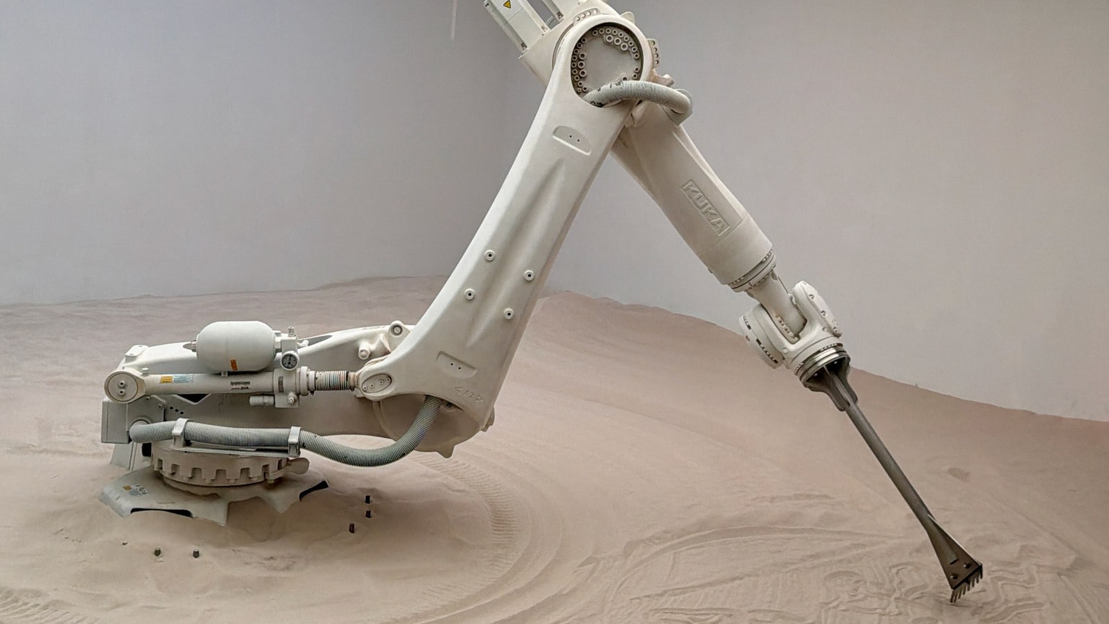
Image credit: Oleg Yunakov — Wikimedia Commons (CC BY-SA 4.0; cropped to 16:9).