On this page
In brief: A camera that finds a part has not yet told the robot where to put its tool. The hard part of vision-guided picking is converting image coordinates into a tool pose in the robot’s own frame, with a known error margin, and deciding what the cell does when that margin is exceeded.
A detection is not a grasp
A vision system can recognise a part and still not know its orientation well enough to pick it. The robot needs a target pose expressed in a defined coordinate frame. It also needs an approach direction that the tool can follow and a path free of collisions with the bin, the fixture and neighbouring parts. Classification accuracy therefore says little about pick success.
The chain of frames from pixel to tool
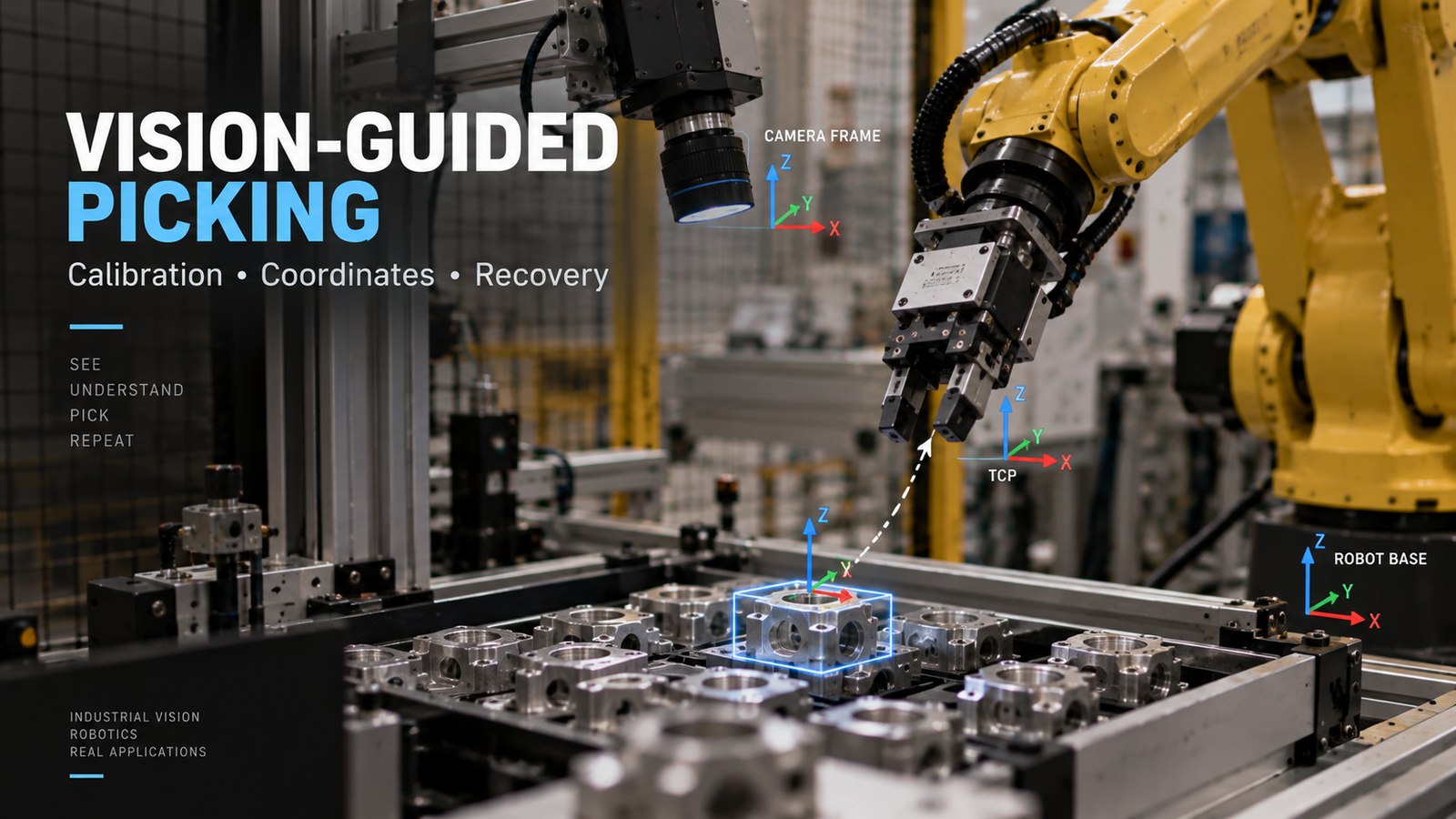
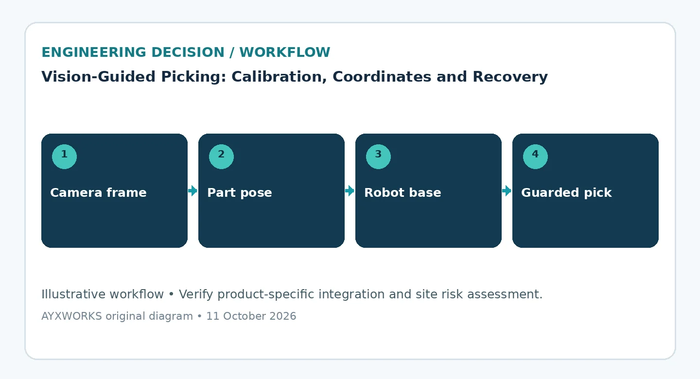
A pick target passes through several coordinate frames: the image, camera, robot base and tool centre point (TCP). Intrinsic calibration describes the camera’s focal length, principal point and lens distortion. The mounting arrangement determines the extrinsic transform: with an eye-in-hand camera, calibration establishes the fixed camera-to-flange or camera-to-tool relationship, and the changing robot pose connects it to the base. With a stationary eye-to-hand camera, the required relationship is camera-to-base. Tool/TCP calibration is another link in that chain. OpenCV documents both arrangements; specify frame names and transform direction rather than using an ambiguous ‘camera-to-robot’ offset.
The errors of every link accumulate at the gripper. A TCP that is slightly wrong produces a position error that changes with tool orientation, which is easy to mistake for a vision fault. Write down units and axis conventions at every interface. A pose sent in metres to a controller that expects millimetres, or with rotation angles in a different order, gives a target that is well formed but wrong.
What invalidates a calibration
Refocusing or changing the lens can change the intrinsic parameters. Moving a camera mount changes its extrinsic relationship; replacing a gripper or re-teaching the TCP can change the tool transform. Review and verify the affected links against known references, and recalibrate those that changed. A TCP change does not, by itself, require new camera intrinsics. Check representative positions and orientations before returning the application to production.
Make uncertainty visible
Reflective surfaces, occlusion, poor lighting and symmetric parts can each produce several plausible poses. The vision system should report a quality measure with every pose, and the cell needs a rule for low values: skip the part, acquire a new image, change how the parts are presented or call the operator. An uncertain detection must never be passed on as a motion target. Use gripper feedback, such as vacuum level, to confirm that the part was actually picked.
Qualify over complete cycles
Count a cycle as successful only when the part reaches its destination in the required orientation. Record retries, no-pick decisions, dropped parts and the time they consume separately, because a cell that succeeds by retrying may still miss its cycle time. Confirm the interface between the vision system and the robot controller in both suppliers’ manuals; a shared camera brand does not guarantee compatible software.
Checklist before committing budget or scope
- Intrinsic calibration of the camera, with a rigid mount and a locked lens.
- Every coordinate transform documented with frame names, units and axis conventions.
- A verified TCP and a grasp approach checked for reach and collisions.
- Written rules for quality thresholds, retries and no-pick decisions.
- A list of events that trigger recalibration, and a quick verification routine.
- Counts of successes, retries and failures over complete cycles with real parts.
What this guide does not establish
This guide is a planning aid. It does not report tests, state the accuracy of any camera or robot, or assess compliance. ISO 10218-2:2025 sets safety requirements for industrial robot applications and robot cells; adding vision does not replace the risk assessment of your cell, and a vision result is not a safety function unless it has been designed and validated as one. The pick accuracy you can achieve has to be measured on your parts, with your equipment, by suitably qualified parties.
Sources and further verification
- ISO — ISO 10218-2:2025, Robotics — Safety requirements — Part 2: Industrial robot applications and robot cells (published 2025-02; catalogue page, the full text is paywalled; accessed 2026-10-11).
- OpenCV — Camera Calibration and 3D Reconstruction (calib3d module, 4.x documentation) (undated API reference; the site blocked automated access, so the content was checked on 2026-10-12 against the module header in the OpenCV source repository).
Next useful step
Bring representative parts or images of them as they are presented, the camera and gripper datasheets, the required placement tolerance and the cycle-time target to the Robotics & Automation page. The AYXWORKS portfolio shows the engineering approach behind these guides. Any project that follows is scoped and delivered through Eurobots/ReBots, and it starts with feasibility and responsibility boundaries, not with an assumed turnkey installation.
Image credit: ayxworks — Original / rights held.