On this page
In brief: Use PROFINET, EtherNet/IP or EtherCAT when a PLC or motion controller must exchange predictable, cyclic process data with a robot, drive or I/O device. Use OPC UA when supervisory software needs structured machine information, and MQTT when events and telemetry must reach multiple applications through a publish/subscribe broker. These technologies are not direct substitutes: a well-designed factory may use several of them together. The best choice depends first on the installed controllers, their licensed interfaces, the required data flow and the consequences of losing communication—not on a headline speed figure.
Engineering guide updated 13 October 2026. This is a standards- and documentation-based comparison, not a laboratory benchmark or a compatibility certification for any specific robot or PLC.
Quick answer: which industrial communication protocol should you use?
| Technology | Best fit | Communication model | Typical robot-cell application | Key limitation or check |
|---|---|---|---|---|
| PROFINET | Machine and factory I/O control | Cyclic real-time I/O; acyclic services | PLC ↔ robot controller, remote I/O, drives | Verify IO-Controller/IO-Device roles, GSDML, RT/IRT requirements and options |
| EtherNet/IP | PLC/device control in a CIP ecosystem | CIP cyclic I/O and explicit messaging over IP networks | PLC ↔ robot controller, gripper, drive or I/O | Verify scanner/adapter support, assemblies, EDS, connection parameters |
| EtherCAT | Fast, tightly synchronized machine-level I/O and motion | On-the-fly processing of EtherCAT frames | Motion drives, distributed I/O, supported robot interfaces | Verify MainDevice/SubDevice roles, ESI, topology and synchronization |
| OPC UA | Structured and interoperable machine information | Client/server and, where implemented, publish/subscribe | Robot status, diagnostics, production data, MES integration | Verify server namespace, security, write permissions and supported profiles |
| MQTT | Event and telemetry distribution | Broker-based publish/subscribe | Machine events, dashboards, analytics, remote telemetry | Define payload semantics, topic ownership, expiry, broker and access policy |
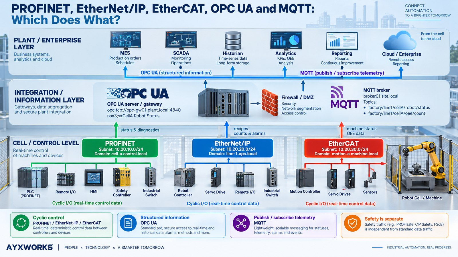
Practical rule: choose the protocol for each interface, not a single protocol for the entire factory. A PLC may control a robot through PROFINET while an edge gateway reads OPC UA data and publishes selected production events through MQTT.
Why Ethernet does not mean every protocol does the same job
Industrial Ethernet is a family of technologies, not one interchangeable communications system. Sharing an RJ45-style connector, Ethernet cable, or even part of the network infrastructure does not guarantee that two devices can understand one another. Their roles, protocol stacks, scheduling behavior, addressing rules and application data differ.
The biggest distinction is between cyclic control data and supervisory information. The first is refreshed repeatedly because the controller needs current input and output states to execute a machine sequence. The second is consumed by software that benefits from history, meaning and context, such as a manufacturing execution system (MES), SCADA screen, maintenance application or analytics service.
A robot may need a new PLC command word every configured I/O interval. A production dashboard may only need to know when the robot starts a cycle, finishes a part or reports a fault. Sending those events through the cyclic I/O map would waste integration effort; using an ordinary MQTT message as the sole mechanism for a time-critical machine interlock would be an architectural mistake.
Determinism is not simply high speed. In control systems, predictability and bounded timing matter as much as average throughput. Actual machine response includes network update time, PLC task scheduling, robot controller processing and application logic. A fast network cannot repair a slow or poorly designed sequence.
1. PROFINET: cyclic control in many PLC-based factories
PROFINET, maintained by PROFIBUS & PROFINET International (PI), is designed for industrial automation with cyclic process data, diagnostics and engineering integration. In a common machine architecture, the PLC is the IO-Controller and the robot controller or remote I/O station is an IO-Device. The PLC exchanges configured input and output data with that device.
How PROFINET communication works
PROFINET supports real-time communication for cyclic I/O. Its commonly discussed classes include RT (Real Time) for many general automation applications and IRT (Isochronous Real Time) for applications with stricter synchronization requirements, where supported. PI also develops PROFINET capabilities involving Time-Sensitive Networking (TSN). These are not interchangeable checkbox features: the required communication capability must be supported by the actual controller, device, firmware and network design.
Besides cyclic I/O, commissioning engineers use device identification, alarms, diagnostics and parameterization. PROFINET device integration normally relies on a GSDML file—an XML-based PROFINET device description. It identifies modules, data sizes and capabilities presented to the engineering software.
Example: PLC to robot over PROFINET
A PLC might send an enable-to-run condition, a program number and a start request. The robot sends back ready, busy, complete and fault information. The signal contract defines what each bit means, which side owns it and how an interrupted cycle is recovered. The PROFINET connection carries the bytes; it does not define the robot manufacturer’s handshake semantics.
Use PROFINET when: your control architecture already uses it, the robot controller provides the required PROFINET device role, and the chosen PLC engineering environment supports the device’s exact GSDML and I/O configuration. Do not assume that PROFINET support automatically includes PROFIsafe, IRT or motion functions.
2. EtherNet/IP: CIP-based control over standard Ethernet/IP networks
EtherNet/IP, maintained by ODVA, carries the Common Industrial Protocol (CIP) using standard Ethernet and Internet protocols. It is widely used for exchanging device I/O and diagnostic information. Despite its similar-looking name, EtherNet/IP is not simply a generic Ethernet connection and is not automatically compatible with PROFINET.
Cyclic I/O versus explicit messages
CIP distinguishes between I/O data exchange—often described as implicit messaging—and request/response access to device objects, often called explicit messaging. Cyclic I/O commonly uses UDP transport; explicit exchanges commonly use TCP. Configured I/O connections carry assemblies of bytes whose meaning depends on the device’s published data model and configuration.
In a typical PLC-to-robot relationship, the PLC acts as an I/O scanner and the robot-side interface acts as an adapter. Exact terminology and supported connection modes vary by vendor and generation. The EDS (Electronic Data Sheet) is a useful device-description resource, but engineers must also check the assembly instances, input/output lengths, connection path and requested packet interval (RPI). An EDS file alone does not guarantee automatic, complete integration.
ODVA also defines related CIP services, such as CIP Safety, CIP Motion, CIP Sync and CIP Security. Their presence in the protocol family does not prove support on a specific robot controller.
Use EtherNet/IP when: the PLC and network architecture use CIP, the robot or end effector supports the correct adapter role, and the connection size, assembly mapping and update requirements can be verified. A quick ping test proves only IP reachability, not an established cyclic I/O connection.
3. EtherCAT: on-the-fly process data and synchronized devices
EtherCAT, supported by the EtherCAT Technology Group (ETG), takes a different approach. The MainDevice sends an EtherCAT frame through a segment. Each SubDevice reads its assigned output data and inserts its input data as the frame passes. This on-the-fly processing reduces repeated per-device exchanges and suits demanding distributed-control applications.
Why EtherCAT differs from ordinary TCP/IP
Standard EtherCAT process-data frames use Ethernet framing, typically identified by EtherType 0x88A4. They are not ordinary TCP or UDP packets. A normal office Ethernet switch, IP router or MQTT broker is not automatically an appropriate part of an EtherCAT real-time segment. Design the network using supported EtherCAT topology elements and devices rather than assuming that any Ethernet hardware will work.
EtherCAT’s Distributed Clocks (DC) mechanism can synchronize compatible devices for coordinated actions, particularly useful across servo drives or other distributed motion components. Actual synchronization performance depends on the implemented devices and machine design.
Configuration commonly uses an ESI (EtherCAT SubDevice Information) XML file. Integrators must check process-data objects, supported operational states, synchronization modes, the EtherCAT state machine and topology. Supporting EtherCAT as a SubDevice does not mean a robot controller can operate as an EtherCAT MainDevice—or the reverse.
Use EtherCAT when: the machine platform is built around EtherCAT, synchronization and distributed motion are relevant, and all selected devices—including any robot interface—support the required roles and process-data mapping. It is not automatically the best choice merely because a brochure advertises a very short bus cycle.
4. OPC UA: machine information with structure and meaning
OPC Unified Architecture (OPC UA), maintained by the OPC Foundation, is a platform-independent industrial communication architecture. It can present machines and their properties as a structured address space rather than just anonymous byte arrays. A client can browse available nodes, read values, subscribe to changing data and, where authorized, call methods or write supported variables.
Why information modelling matters
Imagine an MES needs the robot’s operating mode, currently selected job, active alarm and accumulated part count. A raw PLC I/O array might expose those as offsets and bit numbers, requiring custom decoding. An OPC UA server can expose named values with types and, when modelled, engineering units, descriptions and relationships. That makes integration and later maintenance easier—but only if the server actually implements meaningful, consistent nodes.
For robotics, OPC 40010-1, OPC UA for Robotics – Part 1: Vertical Integration defines a standardized information model intended for higher-level systems. Version 1.02, published 8 September 2025, is listed in the official reference. A vendor may advertise an OPC UA server without implementing this particular companion specification, so verify the namespace and actual node set.
Is OPC UA only for monitoring?
No. OPC UA supports read, write and method capabilities, and it also includes publish/subscribe models. The OPC Foundation’s Field Level Communications / OPC UA FX work extends OPC UA toward field-level applications, including real-time requirements. That is an important technical qualification: in a conventional robot cell, OPC UA is often used above the control network, but it should not be described as categorically incapable of industrial control. Whether a particular OPC UA implementation is suitable for a control role must be established from supported profiles, devices and validated timing.
Use OPC UA when: different platforms need a discoverable, structured and secured view of machine data. Configure certificates, authentication, user permissions, secure endpoints and precise read/write scope. Do not interpret the existence of OPC UA as permission for an MES to command robot motion.
5. MQTT: publish and subscribe to production events
MQTT is an OASIS-standard publish/subscribe messaging protocol. A device or edge application publishes to a topic; a broker distributes messages to interested subscribers. The publisher does not need a direct connection to every dashboard, database or analytics service.
A practical MQTT topic and payload
For example, a gateway may publish to factory/bilbao/cell-03/robot-01/status. One illustrative JSON payload could be:
{
  "schema_version": 1,
  "asset_id": "robot-01",
  "timestamp_utc": "2026-10-13T12:00:00Z",
  "state": "running",
  "program_id": "job-024",
  "parts_completed": 1842,
  "source_quality": "good"
}
Illustrative data only; not measured equipment output. The MQTT specification does not define what state, program_id or parts_completed means. Your integration contract must specify units, data types, timestamps, event identifiers, ownership, schema versions and how consumers identify stale values.
What MQTT QoS actually guarantees
- QoS 0: at most once at the MQTT delivery level; the message may be lost.
- QoS 1: at least once at the MQTT delivery level; duplicates may occur.
- QoS 2: exactly once within the relevant MQTT delivery exchange, with additional protocol overhead. It does not ensure that a downstream database transaction or physical robot action executes exactly once.
Retained messages can be convenient for displaying the last published state, but the last state might be old. Persistent sessions, retries and message expiry also need deliberate configuration. Use timestamps, freshness rules and—where appropriate—event IDs or idempotency keys. For security, use authenticated clients, TLS where applicable, topic-level access-control lists and restricted broker connectivity.
Use MQTT when: you want scalable distribution of operational events, maintenance alerts or historical telemetry. Do not use it as a replacement for a validated PLC–robot cyclic command and safety interface merely because a cloud system can publish a topic.
How these protocols work together in a real robot cell
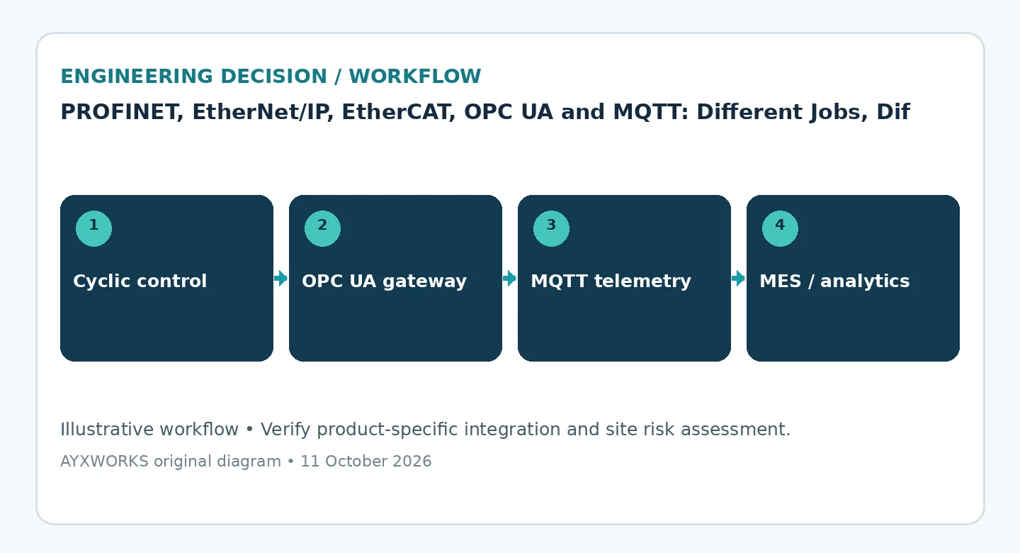
Consider a packaging cell with an industrial robot, a PLC, a gripper, sensors and a supervisory dashboard. A reasonable architecture separates responsibilities as follows:
- Machine control: the PLC exchanges robot commands and status through a supported cyclic fieldbus interface. The robot controller executes its validated robot program. Additional drives or I/O may use that fieldbus or another field-level network.
- Functional safety: a separately engineered safety system supervises protective devices and safe stopping functions. The implementation may use safety-rated hardwired I/O or a supported safety communication protocol, according to the risk assessment.
- Structured operational data: a robot controller, PLC or industrial gateway exposes selected status and diagnostics using OPC UA, with write access constrained by policy.
- Event distribution: an authorized gateway transforms selected operational changes into MQTT events and forwards them to the broker without making the broker part of the machine’s required control loop.
- Business applications: MES, maintenance and analytics software consume information for traceability, OEE analysis and troubleshooting.
This architecture is an example rather than a universal template. Some plants send data directly from the PLC to MES, some use an industrial historian, and some use OPC UA without MQTT. A gateway should solve a real integration need rather than adding another service that could fail.
Worked example: a robust PLC–robot handshake
A communications protocol transports a signal; the interface contract defines the intended machine behavior. Here is an illustrative handshake for a robot performing a single pick-and-place cycle. Bit names and signal directions are conceptual, not an interface standard or manufacturer-specific mapping.
| Signal | Producer | Consumer | Intended meaning |
|---|---|---|---|
ProgramNumber |
PLC | Robot | Job requested for the next cycle |
StartRequest |
PLC | Robot | Requests a cycle when operating conditions allow |
CommandId |
PLC | Robot | Identifies the logical command to prevent ambiguous retries |
Ready |
Robot | PLC | Robot reports it can accept the planned request |
AcceptedCommandId |
Robot | PLC | Confirms which command was accepted |
Busy |
Robot | PLC | Application cycle is executing |
Complete |
Robot | PLC | Application cycle reached its defined completion state |
FaultCode |
Robot | PLC | Reports an application/controller diagnostic condition |
Heartbeat |
Each side, if designed | Other side | Supports application-level stale-data detection |
A possible sequence: the PLC confirms ordinary machine prerequisites, selects the job, presents a new command identifier and requests a cycle. The robot reports which request it accepted, goes busy, and eventually reports completion against the same identifier. The PLC does not issue a new cycle until it has reconciled the previous command and its results. A startup, timeout or lost connection cannot silently convert an old request into a new motion command.
The handshake needs explicit rules for power restoration, emergency stops, protective stops, controller restarts, job changes, simultaneous faults and manual mode. Application Ready or Heartbeat bits are not safety-rated signals unless specifically implemented and validated within an appropriate safety architecture. Never use ordinary fieldbus state alone as proof that the cell is safe.
Do not confuse I/O communication, robot motion and functional safety
Three different engineering questions are often mixed together:
- Standard I/O handshake: exchange start requests, state bits, program numbers and diagnostics. A modest cyclic data block is often sufficient.
- Motion coordination: synchronize multiple axes, conveyor tracking or coordinated robot motions. This may require vendor-specific motion options, synchronized clocks, supported profiles or proprietary interfaces—not simply a faster ordinary I/O cycle.
- Functional safety: detect hazardous conditions and perform validated safety functions. Relevant protocols can include PROFIsafe over suitable networks, CIP Safety and Safety over EtherCAT (FSoE), but only with compatible safety-rated endpoints and the required design and validation.
Safety logic, safety communication, safe torque off, protective stop and emergency stop are not interchangeable concepts. Their use, required performance and recovery behavior follow the machine’s risk assessment and the applicable standards, not a generic network comparison.
How to choose the right protocol: a six-step engineering method
- Map the actual devices. Record exact PLC CPU, robot controller, I/O modules, drives, firmware revisions, network boards and installed software licences. Avoid assuming that a robot brand always includes the same interfaces.
- Define the function. Classify every data item as cyclic command/status, motion-related data, safety-related communication, diagnostics or business telemetry.
- Identify network roles. Verify PROFINET IO-Controller versus IO-Device, EtherNet/IP scanner versus adapter, and EtherCAT MainDevice versus SubDevice. Two devices with the same protocol name but incompatible roles may not communicate directly.
- Request integration evidence. Obtain GSDML for PROFINET, EDS and connection details for EtherNet/IP, or ESI for EtherCAT. For OPC UA obtain supported endpoints, namespaces and security profiles; for MQTT obtain the broker and payload contract.
- Specify timing and failure behavior. Decide what update intervals are required, when data becomes stale, what a timeout means and what machine state follows link loss or restart. Account for PLC scan, robot processing and safety independently.
- Prove the minimal interface on a bench. Establish the connection, exchange representative input/output values, confirm type and byte mapping, then reproduce a dropout and restart before committing the architecture.
Three common procurement scenarios
Scenario A: an existing PROFINET plant. If the chosen robot controller has a supported PROFINET IO-Device option, preserving the plant’s fieldbus may reduce engineering, spare-parts and maintenance complexity. Check the installed option—not just the datasheet.
Scenario B: a CIP-based PLC environment. An EtherNet/IP adapter on the robot may offer the simplest integration. Confirm the exact assemblies, data sizes, RPI and fault behavior before designing the PLC program.
Scenario C: an EtherCAT machine with several servo axes. EtherCAT may be the natural choice for supported drives and I/O. But a separate industrial robot might still use another fieldbus for program-level handshaking if that is what its controller supports. One machine can have more than one legitimate field-level network.
What matters more than advertised cycle times
Vendors sometimes publish impressive theoretical update figures. Those values may be valid for specific supported configurations, but they do not describe the response of your complete robot cell. Compare these separately:
- Fieldbus update interval: how frequently the configured process data are exchanged.
- Jitter: variation in when relevant data or tasks arrive or execute.
- PLC task period: when the controller reads inputs, runs logic and updates outputs.
- Robot controller reaction: when the robot software detects the mapped input and advances its application state.
- Physical response: the additional time required for commanded hardware to react, within the validated machine sequence.
For a conventional start/busy/complete handshake, predictability, diagnosability and compatibility may matter far more than optimizing a small part of the network cycle. For tightly coupled drives and synchronized motion, the balance can change. Use measurements on the intended hardware if timing is critical; do not infer performance from a protocol family name.
Network segmentation, remote access and cybersecurity
Adding OPC UA or MQTT creates useful visibility but also introduces additional access paths. A basic defense-in-depth approach separates the machine’s control network from supervisory and enterprise services, permits only required flows and prevents an analytics outage from becoming a control outage.
- Segmentation: define cell, supervisory and enterprise zones; use routed or firewalled conduits where appropriate.
- Identity: assign separate service identities with limited permissions. Avoid shared default passwords and unrestricted anonymous clients.
- Certificates and encryption: configure supported OPC UA security modes, trusted certificates and MQTT transport security. Monitor expiry and renewal.
- Least privilege: read-only operational exposure by default. Where remote writes are required, put them behind a reviewed and logged command workflow.
- Fail independently: loss of the cloud, broker, historian or SCADA network must not create unsafe machine behavior.
- Maintenance: retain configuration backups, network diagrams, vendor support details and a controlled process for firmware and credentials.
No article can certify a plant’s network security. The precise controls depend on threat modelling, production constraints, applicable requirements and the actual equipment.
Commissioning checklist: tests worth recording
- Device identity: expected controller, firmware, modules and option licences are present.
- Configuration: device file, module order, assembly mappings and byte/bit order match the approved interface.
- Roles and addressing: every interface operates in the intended controller/device or client/server role.
- Normal handshake: job selection, ready, request, accepted, busy and completion agree at both ends.
- Invalid input: unsupported job numbers, malformed values and contradictory command states are rejected or handled safely.
- Loss of communication: unplugging a link or stopping a process produces the specified machine response and alarm; recovery cannot restart a cycle unexpectedly.
- Power restoration: controller, robot and gateway restarts reconcile states and clear stale requests appropriately.
- Data freshness: OPC UA or MQTT subscribers can distinguish current machine state from disconnected or outdated data.
- Access control: unauthorized writes, broker publications and cross-zone connection attempts fail as intended.
- Safety validation: qualified personnel separately verify the actual safety functions, including relevant faults and restart behavior.
Keep a signed-off interface matrix and test results alongside the electrical diagrams, PLC software and robot backups. The next engineer should not need to reverse-engineer what a bit means from a running program.
Frequently asked questions
Which is better: PROFINET or EtherNet/IP?
Neither is universally better. Both are suitable for many PLC-to-robot cyclic I/O interfaces. The existing PLC ecosystem, robot controller options, engineering tools, device roles and service requirements usually determine the practical choice. Confirm integration on the exact hardware instead of deciding from nominal speed alone.
Is EtherCAT faster than PROFINET?
EtherCAT is designed for efficient, deterministic process-data exchange and synchronized devices. PROFINET also offers different real-time mechanisms, including IRT, for demanding applications. Without specifying devices, topology, configured cycles and the complete control task, a generic speed ranking is not a meaningful engineering result.
Can a PLC and robot communicate directly with OPC UA?
Yes, where both implement compatible OPC UA functionality and an application is designed around it. However, having an OPC UA server does not automatically provide an appropriate cyclic robot I/O interface or a validated safety path. Check the precise control requirement and equipment implementation.
Can MQTT start or stop an industrial robot?
An application can technically receive an MQTT command, but MQTT alone does not establish safe, deterministic motion control or safety-rated stopping. Any remote command should pass through specifically designed authorization, PLC or robot state checks, and validated machine controls. Safety functions must not depend on ordinary MQTT delivery.
Can PROFINET, EtherNet/IP and EtherCAT use the same switch?
Do not assume so. Some PROFINET and EtherNet/IP installations can use suitable managed industrial Ethernet infrastructure, subject to protocol, timing and topology constraints. EtherCAT’s usual cyclic communication works differently and requires supported segment hardware. A shared cable type is not proof of network interoperability.
What do GSDML, EDS and ESI files do?
They describe device features to engineering tools: GSDML for PROFINET, EDS for many EtherNet/IP integrations and ESI for EtherCAT. These files help configure process data, parameters and device identity. They are not substitutes for checking firmware compatibility, interface roles and application signal meanings.
Conclusion: choose the control boundary first
For an industrial robot cell, a useful starting architecture is cyclic fieldbus for machine sequencing, separately validated safety functions, structured OPC UA data for supervisory visibility, and MQTT only where brokered event distribution adds value. This is a pattern, not a universal requirement. Successful integration is ultimately determined by the precise controller interfaces, an unambiguous signal contract and tested behavior when something fails.
The most valuable document before purchasing an interface board or software option is often a single page showing who owns every signal, which network carries it, how fresh it must be, and what happens if it disappears.
Sources and further verification
Primary standards-body resources reviewed for this update:
- PROFIBUS & PROFINET International — PROFINET technology, including real-time variants, diagnostics and PROFIsafe.
- PI — GSDML specification for PROFINET, distinguishing PROFINET XML device descriptions from PROFIBUS GSD.
- ODVA — EtherNet/IP, CIP architecture and UDP-based cyclic communication.
- EtherCAT Technology Group — EtherCAT technology, on-the-fly processing, distributed clocks and safety concepts.
- ETG — EtherCAT Compendium, device states, engineering and system implementation topics.
- OPC Foundation — OPC Unified Architecture, information models and security architecture.
- OPC Foundation — OPC UA for Robotics, Part 1, version 1.02, 8 September 2025.
- OPC Foundation — Field Level Communications / OPC UA FX.
- OASIS — MQTT Version 5.0, OASIS Standard, 7 March 2019.
Verification note: these sources establish protocol principles and published specifications. They do not establish the installed options or interoperability of any unnamed PLC/robot pair, nor do they document a performance measurement on a particular factory installation. References checked 13 October 2026.
Planning a robot–PLC integration?
Start with the exact robot controller, PLC model, firmware, fieldbus options and the signals you need to exchange. Explore more practical guides on AYXWORKS Robotics & Automation, including vision-guided picking and recovery. Engineering feasibility and project responsibility boundaries can be discussed through Eurobots/ReBots; learn more about the author in the AYXWORKS portfolio.
Discussion: which connection has caused you the most commissioning trouble—PROFINET device mapping, EtherNet/IP assemblies, EtherCAT configuration, OPC UA security, or MQTT payload consistency?
Inline illustration: AYXWORKS original explanatory diagram. It does not replace a project-specific network schematic. Any separately configured WordPress featured-image credit should be preserved according to the actual image licence.